Soldering PL-259 Coax Connectors
Introduction:
My first
experience with the PL-259 coaxial connecter came into my life when I was in my
teens. Like so many others, my two way radio experience was generated through contact
with the use of Citizens Band
radio back in the early 60's. I remember soldering PL-259 connectors
onto RG-8U type coax but for some reason they never quite turned out looking
like the pictures shown in the instruction manuals. Then one day while I was
visiting a friend and HAM at the Navy's instrument calibration lab in
Tools that I use:
·
Utility knife
·
1/4 inch square, triangular or flat file
(without handle)
·
Small tubing cutter (nylon preferred)
·
Common pliers
·
Wire cutters
·
Soldering rosin (liquid preferred)
·
Weller 240/260 watt soldering gun (or suitable
iron)
·
A good quality 60/40 solder
·
Volt-ohm meter
·
Petroleum jelly or other light lubricant
·
Denatured alcohol (rubbing alcohol)
·
Paper towel or rag
A word about connectors:
There are a lot of connectors on the market. Some connectors are very well made and some are pure junk. I prefer to use connectors that don't have a bright shiny finished on them however a nickel plated shell is fine. These tend to be much more difficult to solder to.
A word about coax cable:
The method described here is intended to be used with RG-8, RG-213 type coax constructed with a solid insulator. It is not recommended to be used with coax constructed with foam type insulation. While there are many coax cables that are 1/2 inch in outside diameter, the true size of the cables that interface directly to PL-259 plugs is 0.405 inches. These instructions will not cover the use of reducers required for adapting the PL-259 to be used with coax such as RG-8X, RG-58 or RG-59.
The Process:
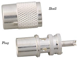
- Start with preparing the PL-259.
- Remove the shell from the plug and set aside.
- Using the handle end of the file insert the tip into each solder hole on the plug and scrape the edge to remove any debris or plating. You should see bare brass.
- Next lay the file flat into the area with the holes and lightly remove any burs created from cleaning out the holes. At this time you may want to remove the plating finish around the holes exposing the brass material.
- Next let's move to the coax and prepare it for accepting the connector.
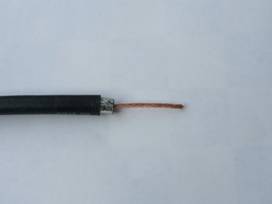
- Remove about 2 inches of the coax outer covering known as the jacket. Do this with a sharp utility knife making sure not to nick the wire braid below it. The best method I've found using a utility knife is to score the jacket then bend the coax slightly. This will allow the scored area to split lessening the chances of nicking the braid below it. This may take a little patience at first but with practice it will become easier. If you nick the braid, cut off the coax and start over. Remember, RF travels on the outside of this braid too. By the way, there are special coax cutters manufactured specifically for this purpose but they are in the $50 to $100 price range. The choice is yours.
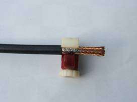
- Apply one or two drops of rosin on the newly exposed braid close to the jacket. Use the rosin sparingly and don't overdo it. A little goes a long way. The purpose of this step is to allow the solder used in the next step to flow quickly lessening the heat exposure time when applying the solder.
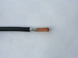
- Using your soldering gun or iron, apply just enough solder to wick onto the braid from the jacket toward the end of the coax covering about 1/2 to 3/4 inch all the way around the diameter of the braid.
- Let the solder and coax cool.
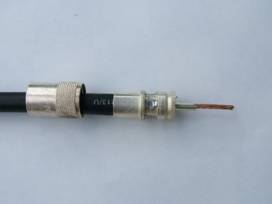
- Using the tubing cutter, position the outer edge of the tubing cutter housing against the end of the coax jacket. This should position the cutting wheel of the tubing cutter the proper distance away from the end of the coax jacket allowing just enough tinned braid to remain after cutting. Continue adjusting the cutter deeper as you rotate the cutter. This will cut through the coax braid and dielectric material. Continue until you have run out of adjustment with the tubing cutter wheel.
- Remove the tubing cutter from the coax. You will notice that the cutting wheel will most likely not reach the center conductor of the coax.
- Take the utility knife and gently cut into the cut the tubing cutter made. Cut into the dielectric carefully making sure you do not nick the center conductor. If you nick the center conductor, cut off your work and start over.
- Once you have cut close to the center conductor you can pull on the scrap end of the coax removing the excess braid, dielectric material exposing the center conductor. This may have to be accomplished with some force or the use of pliers on the scrap end. A slight twisting motion in the natural twist of the center conductor while removing the scrap may also help.
- Now you should have the coax with about 3/8 inch tinned section exposed along with about 1 1/2 inch of exposed center conductor. You are now ready to install the PL-259 connector.
- Place the shell of the connector on the coax in the proper direction. (The threaded end facing the end of the coax you just prepared). DO NOT FORGET THIS STEP !!!!
- Apply a very small amount of lubricant on the jacket. (cover about ¼ inch in length and all the way around the end of the jacket) This will help lubricate the plug as it screws over the jacket in the next step.
- Place the plug of the PL-259 on the end of the coax and screw the plug on until it bottoms onto the coax. At this point you may want to back the plug off the coax about 1/8 turn. This will give the coax a little gap between the dielectric and the insulator inside the plug.
- Looking through the holes in the connector plug you should see the tinned braid. Apply enough solder into each hole to ensure a good electrical connection. Don't get carried away with the heat from the soldering gun or iron. Also ensure that all holes are completely sealed with solder to help prevent water from getting into the holes.
- At this point you may want to lightly try to turn the plug on the coax. If the plug turns it hasn't been soldered properly and additional solder needs to be added to each hole.
- Next check for continuity (a short) between the coax center conductor that should be protruding out of the connector pin and the body of the connector plug. You are checking for no continuity (an open) between these two points. I've deliberately not soldered the center pin prior to making this first check. This is so it will be easier to remove the connector if you find a short at this time.
- Next check for continuity between the body of the plug and the shield at the opposite end of the coax if possible. You should have a good electrical connection.
- If all is well, than solder the center connecter pin to the center conductor of the coax.
- Clip off the excess center conductor at the tip of the connector pin and ensure you have a good solder connection. Add a little more solder to the tip.
- Check for a short between the center pin and the body of the plug of the connector. If there is continuity at these two points then you have a shorted plug and you will have to start over. If you wait to make these checks after you have installed both connectors, you will not know which end has the bad connection. You will have a 50/50 chance of being correct in your guess as to which one is bad so test each connector as you install them.
- After all the connectors have been installed and checked for proper continuity, clean off the excess rosin with the alcohol and screw the shells onto the connector plugs.
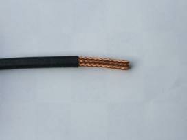
Remove about 2
inches of the
jacket. Tin
about 3/8 inch close
to the jacket.
Place the tubing cutter against the jacket. Cut into the tinned braid/dielectric and remove.
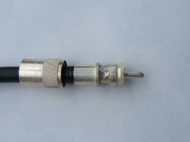
Install the shell then screw the plug onto the coax. Now solder the plug to the tinned After checking continuity and plug security, cut off excess center conductor and
braid through the plug holes. solder the tip.